
Project
Summary
Working with Spacelab LLC space startup (#1 space startup of Kazakhstan) I participated in development of one of their side projects, with internal name “Valve Sensor”.
Problem
My goal was to develop an algorithm allowing detect rotation of pipeline valve. This algorithm should work on a physical gadget, attaching to a valve handle. Gadget should be “plug and play” (just stick it to handle, calibrate, and let it work), should use an off-the-shelf electronic components and should be cheap. So, I need to get information about rotation valve from standard 9-axis IMU. Also this algorithm must use different physical principles and math than algorithms of company Aloxy (that was request of my partners from SpaceLab).
Solution
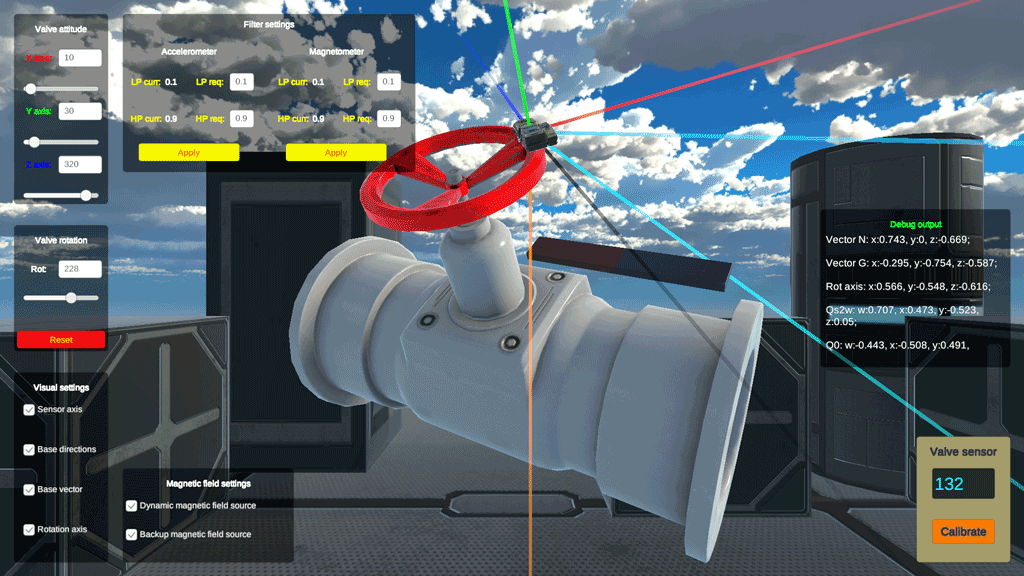
As an astrodynamicist, I understood that I need to use quaternion math in this case. But same time, as an ACDS developer, I knew amount of pain I would face with this quats later if I would try to deal with this task “hurriedly”. So, as experienced game developer, I used Unity to create digital twin of real pipeline valve, and developed an algorithm using this twin as a test installation.
And that was extremely good decision! Unity is great to create digital twins of such stuff. It is game development tool, but it is powerful, simple and fast enough when you need to focus on a problem and make a prototype rapidly!
Result
Sadly, at fall 2024 SpaceLab did not find funding at moment we developed the prototype of the sensor. So I left the project and published the algorithm under MIT-alike lincese on GitHub (now this repository moved here).
First place on Digital Bridge 2025
In October, 2025 SpaceLab “Valve Sensor” project won the Industry 4.0 Pitch Battle competition held as part of the Digital Bridge 2025 international forum in Astana.
I am proud and pretty glad that algorithm developed by me helped SpaceLab LLC to achieve this great success!
Algorithm
The core idea of an algorithm was to use available and easily detectable physical effects (gravity pull and geomagnetism) to form a basis of the “world” coordinate system.
Algorithm was separated in two steps – calibration and rotation detection.
Calibration
On calibration, at first step I formulated default axes of “sensor” coordinate system:
Then, I formulated “constant” axis (rotation around which is less probable) as:
From this I calculated rotation from one of “sensor” axes to constant axis:
After this, I formulated default “word” axes, gathering data from 9-axis IMU sensor; first, X axis from vector to “magnetic north” (or any other stable magnetic direction):
Then, Y axis from inverted gravity direction:
Then, Z axis I expressed as:
From this I gathered “world” constant axis:
Now, rotation from “sensor” to “world” will be:
Now, to simplify calculation of default rotation, let’s introduce so-called “handle” vector (vector connecting valve rotation axis and sensor position):
From here, default quaternion of rotation will be:
Rotation detection
To calculate current sensor rotation, we should start with setting “sensor” axis:
Then, set current “world” axis, gathering data from 9-axis IMU sensor:
Same as on calibration, define “handle” vector as:
Now, current quaternion of rotation will be:
Now, it is easy to calculate quaternion of true rotation, which will be:
From this it’s elementary to get valve turn angle utilizing quaternion, axis and angle relations.
Source code
C# source code of an algorithm is provided at GitHub repo.
Digital twin
Digital twin web app available here.